 |
 |
 |
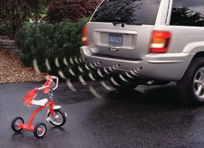
| This new safety system was introduced for the Jeep Grand Cherokee U.S. Market in the spring of 2003 and can be installed in all WJ models from 1999-2004. The park distance Sensors help maneuvering in and around parked cars and tight spaces. It will detect objects in the vehicle's path up to six feet away. Four ultrasonic paintable sensors are discreetly integrated into the rear bumper, activating an interior light/sound indicator when vehicle is in reverse. An LED display is mounted on the interior D-pillar (cargo area) which can be seen through the rear view mirror. |
| Grand Cherokee Reverse Sensing System parts | ||
| Item | Part # | MSRP |
| Mopar Reverse Sensing System kit | 82208247AB | $299.00 |
| Hole saw tool
(24mm and 30mm holesaws for sensors and display installation) |
82208882 | $25.00 |
|
The installation notes shown below are also printed in the available PDF installation manual (link below). They are reprinted here for convenience and to give anyone interesting in buying this system an idea of what is involved for the installation. Tools required are shown below on the scan of page one of the manual. Although not a particularly difficult installation, it is best left for professionals or those who have experience in this type of automotive work. Installation involves removing interior trim panels, removing the rear fascia, drilling holes, and soldering a couple of wires to the taillamp harness. It is highly suggested to puchase the Mopar holesaws as being metric they may be hard to find at the local hardware store.
2. Remove the right (passenger’s side) D-pillar trim panel. 3. Install audio/visual display to the right D-pillar trim panel as shown. 4. Remove the rear fascia and place it on a protected surface. 5. If painting the sensors to match the vehicle color is desired by the customer, refer to the following four steps:
6. Install sensors as shown and fully engage the clips. Attach the sensor cables. 7. Re-install rear fascia while carefully pulling the sensor cable connectors one at a time into the vehicle. Keep cables away from sharp edges and ensure they are not pinched under the fascia. Replace any damaged plastic pop rivets from stock. 8. Route power harness wires through the right taillamp harness grommet as shown. 9. Determine which taillamp wires have the ground and back-up lamp signals. Disconnect the negative battery cable and perform center splicing as shown. 10. Use RTV sealant on any altered grommets to prevent water leaks. 11. Connect audio/visual display cable to the extension cable. 12. Make all connections to the controller. Install controller using hook and loop patches and screws. 13. Loop up slack in cables and wires. Apply tie straps and stow away neatly. Do not kink or tightly coil the cables. 14. Re-connect battery and check operation of the reverse sensing system. 15. The audio/visual display can be set to NO AUDIO, LOW AUDIO, or HIGH AUDIO.
|