 |
|
| Front wiper system | Front components | Front operating modes |
| Rear wiper system | Rear components | Rear operating modes |
| Front blade and arm removal | Rear blade and arm removal |
 |
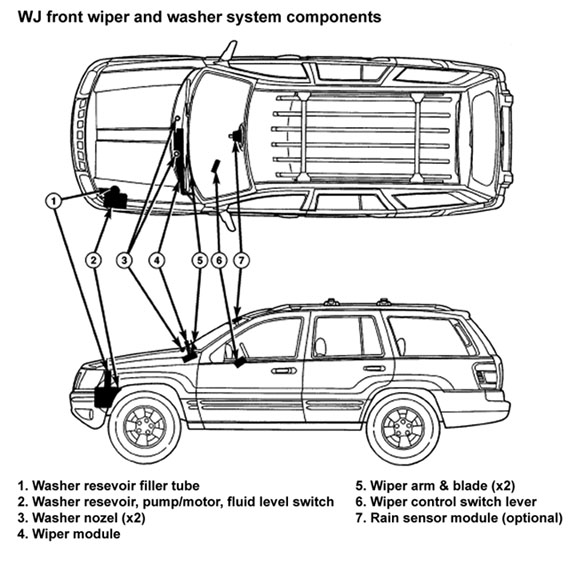
An electrically operated intermittent front wiper and washer system is standard factory-installed safety equipment on all WJ models. A Rain Sense wiper system was introduced starting with the 2002 model year (standard on Overland's and optional on Limited's).
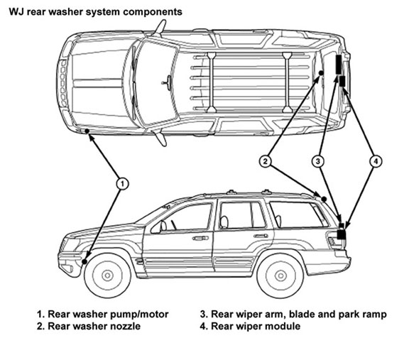
An electrically operated fixed interval intermittent rear wiper and washer system is standard factory-installed equipment on all WJ models.
Front blade removal:
1. Lift the front wiper arm to raise the wiper
blade and element off of the glass, until the wiper
arm hinge is in its over-center position.
2. To remove the wiper blade from the wiper arm,
depress the pivot block latch release tab under the
tip of the arm and slide the blade away from the tip
towards the pivot end of the arm far enough to disengage
the pivot block from the hook formation on
the end of the arm.
4. Extract the hook formation on the tip of the
wiper arm from the opening in the wiper blade
superstructure just ahead of the wiper blade pivot
block/latch unit.
CAUTION: Do not allow the wiper arm to spring
back against the glass without the wiper blade in
place or the glass may be damaged.
5. Gently lower the tip of the wiper arm onto the
glass.
NOTE: The notched end of the wiper element flexor
should always be oriented towards the end of the
wiper blade that is nearest to the wiper pivot.
1. Lift the front wiper arm off of the windshield
glass, until the wiper arm hinge is in its over-center
position.
2. Position the front wiper blade near the hook
formation on the tip of the arm with the notched end
of the wiper element flexor oriented towards the end
of the wiper arm that is nearest to the wiper pivot.
3. Insert the hook formation on the tip of the
wiper arm through the opening in the wiper blade
superstructure ahead of the wiper blade pivot block/
latch unit far enough to engage the pivot block with
the hook.
4. Slide the wiper blade pivot block/latch up into
the hook formation on the tip of the wiper arm until
the latch release tab snaps into its locked position.
Latch engagement will be accompanied by an audible
click.
5. Gently lower the wiper blade onto the glass.
2. Carefully pry the plastic nut cap off of the pivot end of the wiper arm.
3. With a 15mm socket, remove the nut that secures the wiper arm to the wiper pivot shaft.
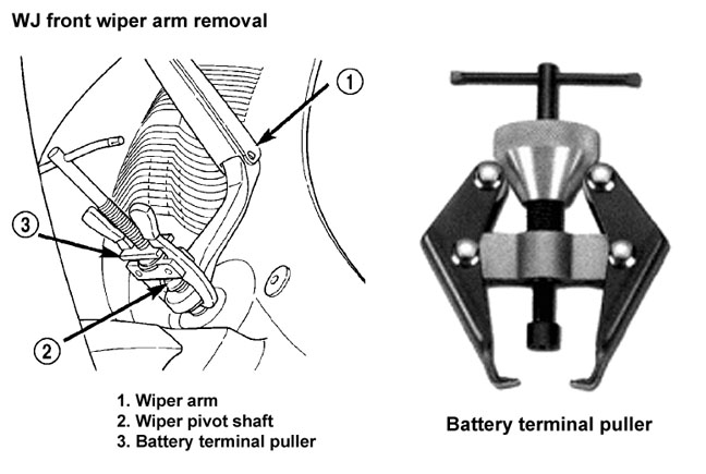
4. If necessary, use a suitable battery terminal puller to disengage the wiper arm from the wiper pivot shaft
5. Remove the front wiper arm pivot end from the wiper pivot shaft.
NOTE: Be certain that the wiper motor is in the park
position before attempting to install the front wiper
arms. Turn the ignition switch to the On position
and move the right (wiper) multi-function switch
control knob to its Off position. If the wiper pivots
move, wait until they stop moving, then turn the
ignition switch back to the Off position. The wiper
motor is now in its park position.
1. The front wiper arms must be indexed to the
wiper pivot shafts with the wiper motor in the park
position to be properly installed. Position the front
wiper arm pivot ends onto the wiper pivot shafts so
that the lower edge of the blade is aligned with the
wiper alignment lines located in the lower edge of
the windshield glass.
2. Once the wiper blade is aligned, lift the wiper
arm away from the windshield slightly to relieve the
spring tension on the pivot end and push the pivot
hole on the end of the wiper arm down firmly and
evenly over the wiper pivot shaft.
3. Install and tighten the nut that secures the
wiper arm to the wiper pivot shaft. Tighten the nut
to 24 N·m (18 ft. lbs.).
4. Wet the windshield glass, then operate the
front wipers. Turn the front wipers Off, then check
for the correct wiper arm position and readjust as
required.
5. Reinstall the plastic nut cap onto the wiper arm pivot nut.
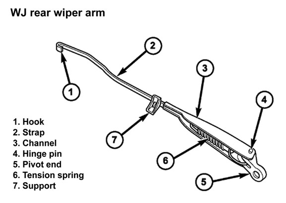
Rear blade removal:
1. Disengage the rear wiper arm support from the rubber rear wiper arm park ramp on the right side of the liftgate just below the liftgate flip-up glass.
2. Lift the rear wiper arm to engage the arm hinge in its over-center position with the wiper blade and element off of the liftgate and the glass.
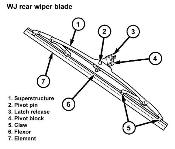
3. To remove the wiper blade from the wiper arm, push the pivot block latch release tab under the tip of the arm and slide the blade away from the tip towards the rear wiper motor output shaft end of the arm.
4. Slide the rear wiper blade away from the tip of the arm towards the pivot end of the arm far enough to disengage the pivot block from the hook formation on the end of the arm.
5. Extract the hook formation on the tip of the wiper arm from the opening in the wiper blade superstructure ahead of the wiper blade pivot block/latch unit.
CAUTION: Do not allow the wiper arm to spring back against the liftgate or the glass without the wiper blade in place or they may be damaged.
6. Gently lower the wiper arm and place the arm support in the park ramp.
NOTE: The notched end of the wiper element flexor should always be oriented towards the end of the wiper blade that is nearest to the rear wiper motor output shaft.
1. Lift the rear wiper arm off of the liftgate park
ramp.
2. Position the rear wiper blade near the hook formation on the tip of the arm with the notched end of the wiper element flexor oriented towards the end of the wiper arm that is nearest to the rear wiper motor output shaft.
3. Insert the hook formation on the tip of the wiper arm through the opening in the wiper blade superstructure ahead of the wiper blade pivot block/ latch unit far enough to engage the pivot block with the hook.
4. Slide the wiper blade pivot block/latch up into the hook formation on the tip of the wiper arm until the latch release tab snaps into its locked position.
5. Gently lower the wiper arm and place the arm support on the park ramp.
2. Using a 13mm socket or wrench, remove the nut that secures the rear wiper arm to the rear wiper motor output shaft.
3. Lift the rear wiper arm far enough to engage the over-center arm hinge in its upright position to hold the wiper blade off of the liftgate.
4. If necessary, use a battery terminal puller to disengage the wiper arm from the rear wiper motor output shaft splines.
5. Remove the rear wiper arm pivot end from the motor output shaft.
1. The rear wiper arm must be indexed to the motor output shaft with the rear wiper motor in the park position to be properly installed. Place the wiper arm onto the liftgate with the wiper arm support positioned on the park ramp and the tapered mounting hole on the pivot end of the arm positioned over the rear wiper motor output shaft.
2. With the wiper arm in the Installation Position, push the tapered mounting hole on the pivot end of the wiper arm down over the rear wiper motor
output shaft.
3. Install and tighten the nut that secures the rear wiper arm to the rear wiper motor output shaft. Tighten the nut to 18 N·m (13 ft. lbs.)
4. Reinstall the plastic nut cap over the nut on the rear wiper motor output shaft end of the rear wiper arm.
5. Lift the rear wiper arm support away from the park ramp, then place the wiper arm support in the park ramp in the Park Position.
Front wiper and washer system
Rear wiper and washer system
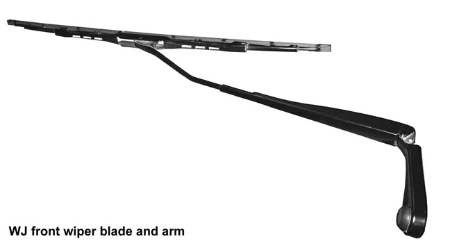

NOTE: All Grand Cherokee WJ models have two 20.67 inch windshield wiper blades with
non-replaceable rubber elements (squeegees). The wiper blades cannot be adjusted or repaired. If faulty, worn, or damaged the entire wiper blade unit must be replaced.
Front blade installation:
Front arm removal:
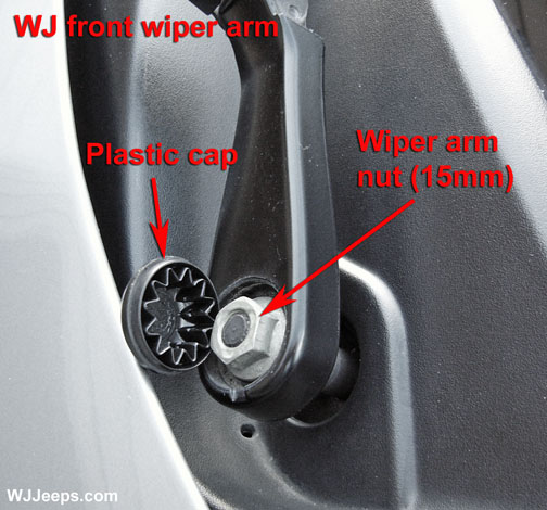
1. Lift the front wiper arm to its over-center position to hold the wiper blade off of the glass and relieve the spring tension on the wiper arm.
Front arm installation:
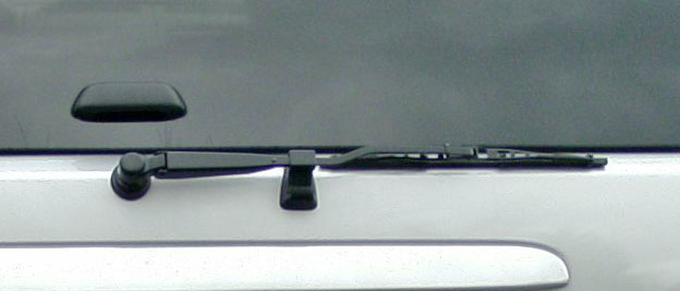
NOTE: All Grand Cherokee WJ models have a single 12-inch rear wiper blade with a
non-replaceable rubber element (squeegee). The wiper blade cannot be adjusted or repaired. If faulty, worn, or damaged the entire wiper blade unit must be replaced.
Rear blade installation:
Rear arm removal:
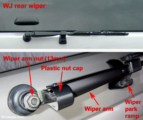
1. Carefully pry the plastic nut cap off of the nut on the rear wiper motor output shaft end of the wiper arm. This can usually be done without a tool.
Rear arm installation: