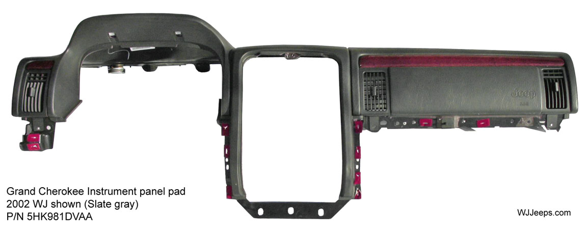
Part 1 - Instrument panel assembly removal
NOTE: Before starting this procedure, be certain to turn the steering wheel until the front wheels are in the straight-ahead position.
WARNING: ON VEHICLES EQUIPPED WITH AIRBAGS, DISABLE THE AIRBAG SYSTEM BEFORE ATTEMPTING ANY STEERING WHEEL, STEERING COLUMN, OR INSTRUMENT PANEL COMPONENT
DIAGNOSIS OR SERVICE. DISCONNECT AND ISOLATE THE BATTERY NEGATIVE (GROUND) CABLE, THEN WAIT TWO MINUTES FOR THE AIRBAG SYSTEM CAPACITOR TO DISCHARGE BEFORE PERFORMING FURTHER DIAGNOSIS OR SERVICE. THIS IS THE ONLY SURE WAY TO DISABLE THE AIRBAG SYSTEM. FAILURE TO TAKE THE PROPER PRECAUTIONS
COULD RESULT IN AN ACCIDENTAL AIRBAG DEPLOYMENT AND POSSIBLE PERSONAL INJURY.
1. Disconnect and isolate the battery negative cable.
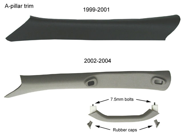
2. Remove the trim from the right and left A-pillars (Fig. 1).
Figure 1
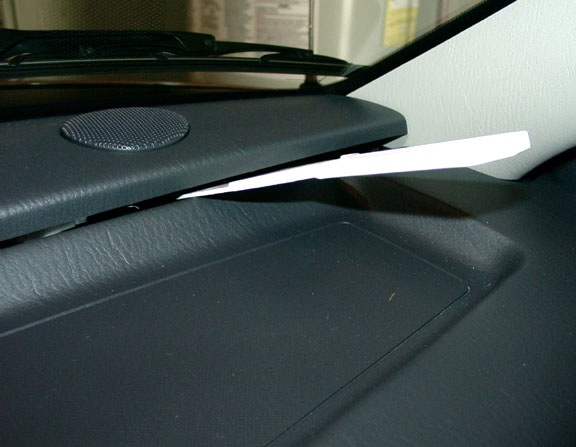
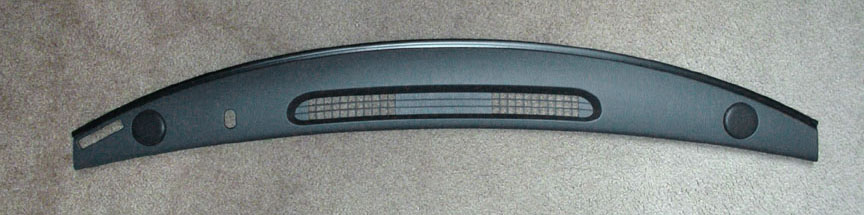
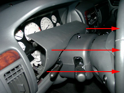
3. Remove the instrument panel top cover. With a wide flat tool (3" plastic putty knife or similar, gently pry the dash trim panel upwards starting at either end. You can then get your fingers under the lip and lift it up, working your way to the opposite end. The trim is held in place by four spring clips. There are no parts or wires attached to the trim cover. (Fig. 2 & 3).
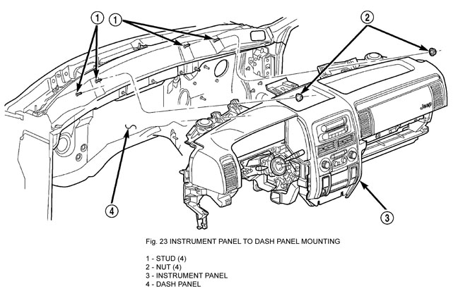
4. Remove the four nuts that secure the instrument panel to the studs on the dash panel near the windshield fence line (Fig. 23). Unclip the defrost ducts from the dash assembly.
5. Remove the scuff plates from the right and left front door sills. These are attached with spring clips and can be removed grasping them underneath a corner and carefully lifting them up.
6. Remove the lower trim panels from the right and left inner cowl sides by removing the screws attaching cowl trim to floor. Remove plastic nut. Grasp cowl trim and pull outward to separate from clip.
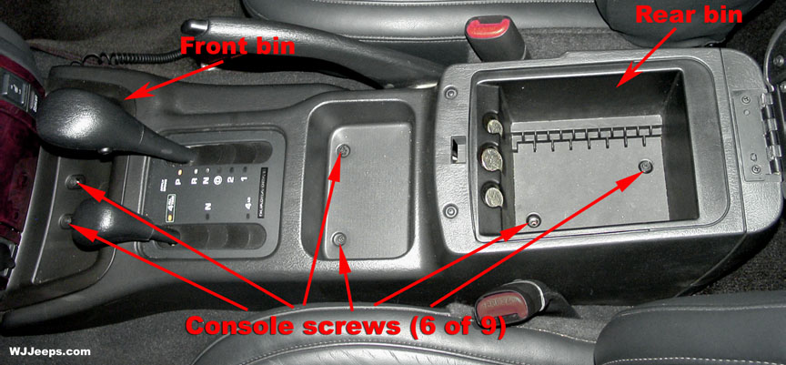
7. Remove the console from the floor panel transmission tunnel (Fig. 4 & 5).
|
A. Set parking brake.
B. Place the transmission shift lever and transfer case shift lever in full rearward position (toward back of vehicle).
C. Remove mat from front bin and remove the two screws attaching the bin to the floor. Remove the bin by slightly prying up on it with a trim stick or small screwdriver.
D. Remove the rubber cupholder and remove the two screws underneath it.
E. Remove the two screws inside the bottom of the rear bin and remove the bin.
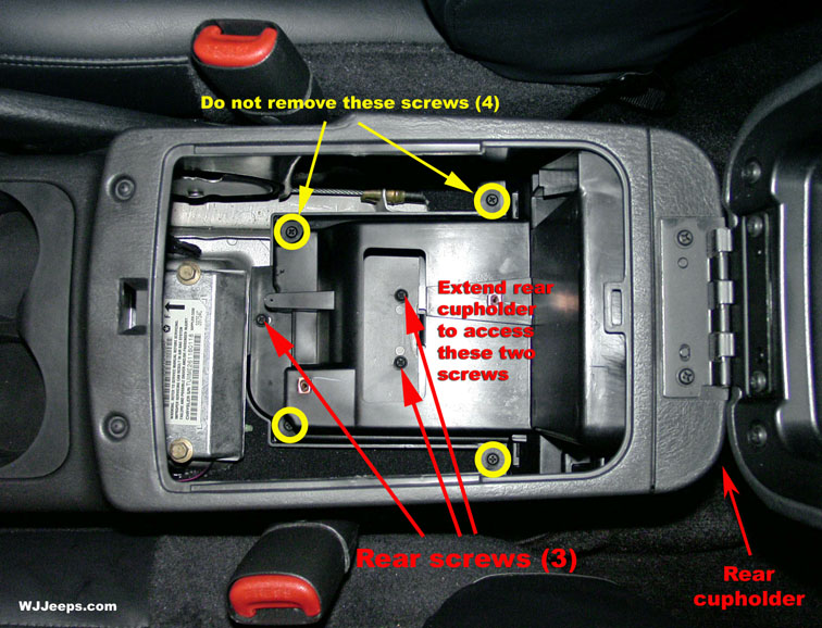
F. Pull the rear passenger cupholder outward to access and remove the three screws attaching the rear of the console to the floor (2 under the cup holder and 1 just in front), as shown in the photo above right.
G. Carefully lift the console upward and rearward to remove from vehicle.
|
8. Remove the plastic fuse cover from the junction block on the lower left side of the instrument panel. It is held on with plastic tabs and can easily be pulled off by pulling downward.
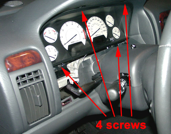
9. Remove the cluster bezel. The cluster bezel lower trim piece is held in place by 4 spring clips, one at each corner. Pull straight out to remove. On the left side, you can reach your thumb behind the bezel at the tilt wheel lever indentation and pull forward. If so equipped, you'll need to unhook the Adjustable Pedals harness from the back of the bezel. (Fig. 6 & 7)
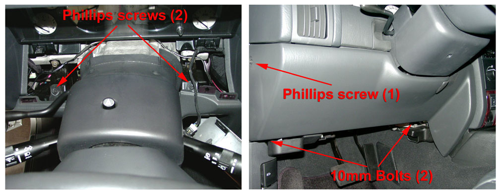
10. Remove the steering column opening cover. The cover is held in place by three screws, two bolts and three spring clips. (Fig. 8).
|
A. Remove the two screws at the inside top of the lower trim bezel.
B. Remove the phillips screw on the left side and the two 10mm bolts underneath the bezel trim.
C. Pull the steering column opening cover rearward to disengage the three snap clips (one outboard and two inboard) that secure it to the receptacles in the instrument panel. The clips are very snug, requiring a fairly strong pull on each side. When replacing the cover, be certain to align the two plastic guide pins as well as the spring clips before pushing it back into place.
|
Figure 8
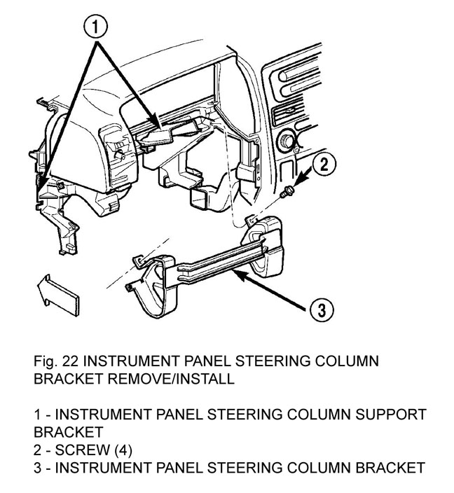
11. Remove the four screws that secure the steering column bracket to the instrument panel steering column support bracket (Fig. 22).
Figure 22
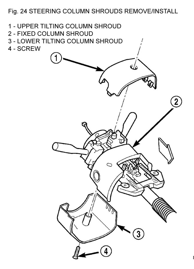
12. Remove the screw that secures the lower tilting steering column shroud to the steering column multi-function switch mounting housing (Fig. 24).
13. Unsnap the two halves of the tilting steering column shroud from each other and remove both halves from the steering column.
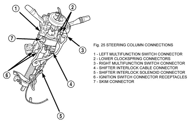
14. Disconnect the instrument panel wire harness connectors from the following steering column components (Fig. 25):
- The two lower clockspring connector receptacles
- The left multi-function switch connector receptacle
- The right multi-function switch connector receptacle
- The two ignition switch connector receptacles
- If equipped, the shifter interlock solenoid connector receptacle
- If equipped, the sentry key immobilizer module (SKIM) connector receptacle.
15. Turn the ignition switch to the On position, then release and remove the shifter interlock cable connector from the ignition lock housing receptacle.
16. Turn the ignition switch back to the Lock position to prevent steering wheel rotation and the loss of clockspring centering following steering column removal.
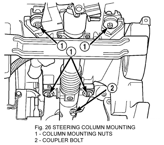
17. Remove the bolt that secures the coupler to the lower steering column shaft (Fig. 26).
18. Remove the four nuts that secure the steering column to the studs on the instrument panel steering column support bracket.
19. Remove the steering column from the instrument panel. Be certain that the steering wheel is locked and secured from rotation to prevent the loss of clockspring centering.
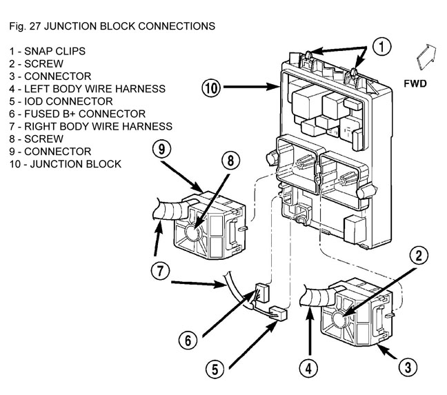
20. Disconnect the left and right body wire harness connectors, the ignition off draw (IOD) wire harness connector and the fused B(+) wire harness connector from the connector receptacles of the JB (Fig. 27).
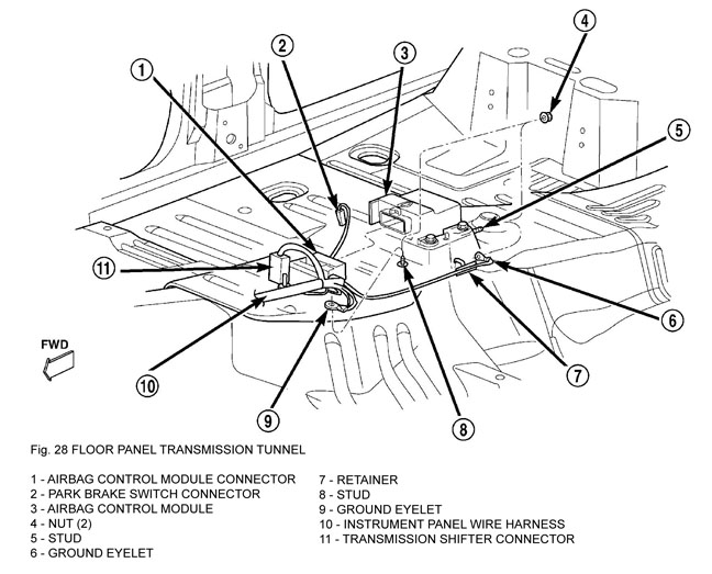
21. Disconnect the instrument panel wire harness connectors from the following floor panel transmission tunnel components (Fig. 28):
- The airbag control module (ACM) connector receptacle
- The park brake switch terminal
- The transmission shifter connector receptacle.
22. Remove the two nuts that secure the instrument panel wire harness ground eyelets to the studs on the floor panel transmission tunnel in front of and behind the ACM.
23. Disengage the retainers that secure the instrument panel wire harness to the floor panel transmission tunnel.
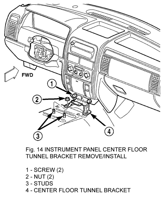
24. Remove the instrument panel to center floor tunnel bracket from the instrument panel and the floor panel transmission tunnel (Fig. 21).
Figure 21
25. Remove the one screw that secures the floor duct to the heater and air conditioner housing near the driver side of the floor panel transmission tunnel and remove the duct from the housing.
26. If the vehicle is equipped with the manual heating and air conditioning system, disconnect the vacuum harness connector located near the driver side of the floor panel transmission tunnel behind the driver side floor duct.
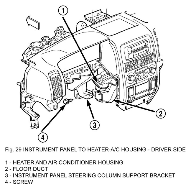
27. Remove the one screw that secures the instrument panel steering column support bracket to the driver side end of the heater and air conditioner housing (Fig. 29).
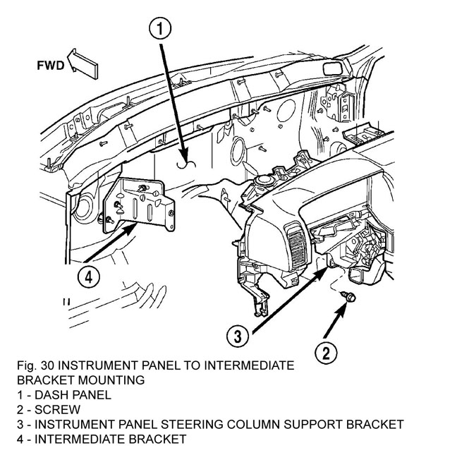
28. Remove the one screw that secures the instrument panel steering column support bracket to the intermediate bracket on the driver side dash panel (Fig. 30).
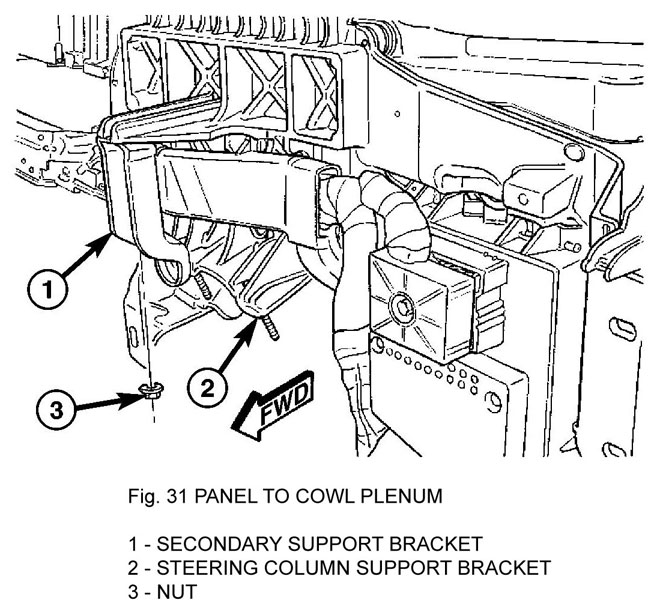
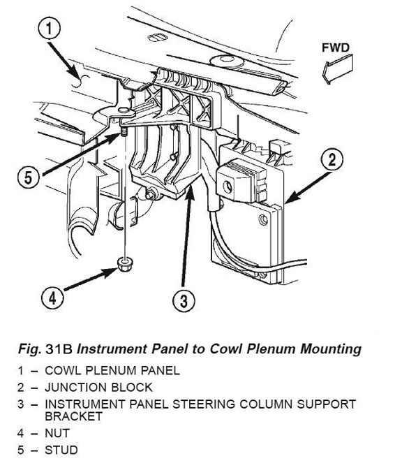
29. Remove the nut that secures the instrument panel steering column support bracket to the stud on the driver side cowl plenum panel (Fig. 31 or 31B).
(On earlier models there is a steel bracket between these two pieces as in the picture. Removing the nut wont let the support bracket loose, you need to leave the nut and remove the bolt from the steel bracket to the back of the support bracket).
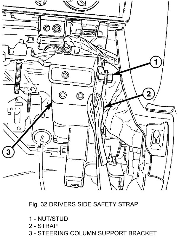
30. Remove the nut and disconnect the safety strap from the support bracket (Fig. 32).
Figure 31
| |
Figure 31B
| |
Figure 32
|
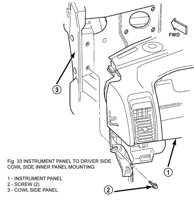
31. Remove the two screws that secure the instrument panel to the driver side cowl side inner panel (Fig. 33).
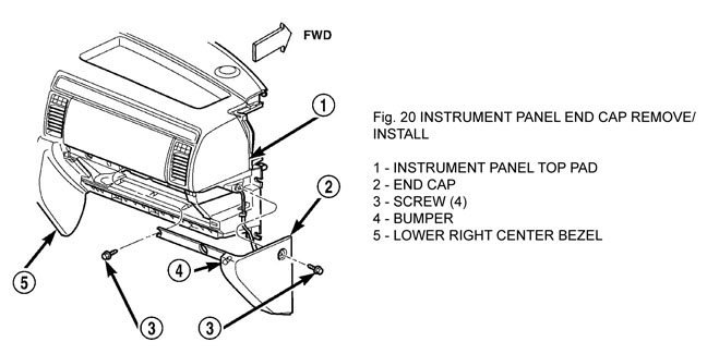
32. Remove the end cap (Fig. 20).
A. Unlatch and open the glove box.
B. Remove the one screw that secures the outboard end of the end cap to the instrument panel top pad.
C. Remove the three screws that secure the end cap to the instrument panel glove box opening.
D. Pull the end cap straight back from the instrument
panel to disengage the one snap clip that secures it to the receptacle in the instrument panel
E. Remove the end cap from the instrument panel.
|
Figure 20
33. Remove the lower right center bezel.
34. Remove the glove box.
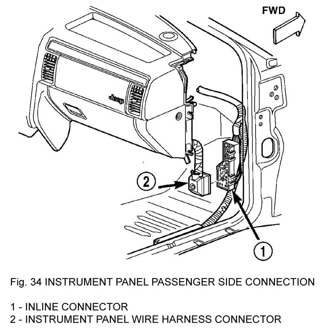
35. Disconnect the instrument panel wire harness connector from the lower cavity of the inline connector on the passenger side cowl side inner panel (Fig. 34).
36. Disconnect the two halves of the radio antenna coaxial cable connector near the right cowl side inner panel under the end of the instrument panel.
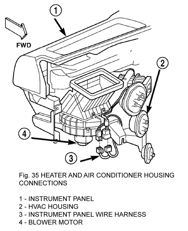
37. Disconnect the two instrument panel wire harness connectors from the two heater and air conditioner housing connectors located near the blower motor on the passenger side end of the housing (Fig. 35).
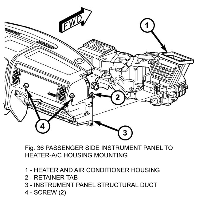
38. Remove the two screws that secure the passenger side instrument panel structural duct to the heater and air conditioner housing (Fig. 36).
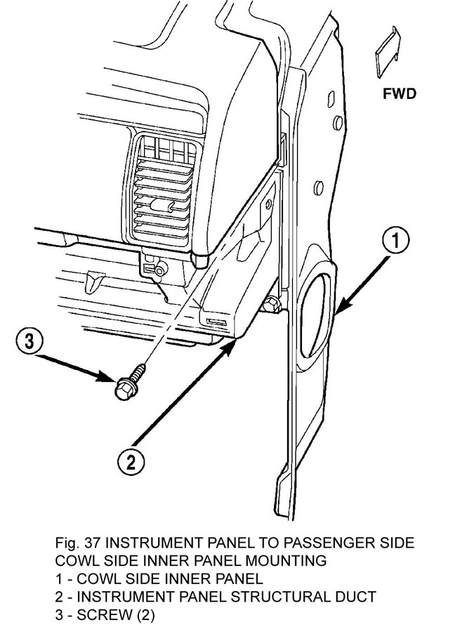
39. Remove the two screws that secure the instrument panel to the passenger side cowl side inner panel (Fig. 37).
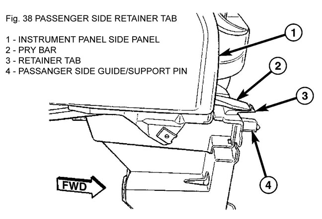
40. Depress the tab on the passenger side and with the aid of an assistant, lift the instrument panel assembly upward off of the studs on the dash panel near the windshield fence line and pull the instrument panel rearward from the dash panel and the cowl side inner panels and remove it through the driver side front door of the vehicle (Fig. 38).